How to make a kaleidoscope in NodeBox 3
A kaleidoscopic image is an image generated from another image through mirroring and rotational symmetry. Interesting and unexpected results can be achieved by tweaking a small number of parameters. Sounds like the perfect job for NodeBox!
For this tutorial it’s important to have a good understanding about subnetworks.
- First we need an image source. Since for now we’re limited to using vector shapes you can either create your own vectors (in NodeBox or elsewhere) or use an svg file from sowewhere else. The one I used in this tutorial is cartoon apple with worm from openclipart.org.
- Create a new folder and store your svg file there (if your’re just using vectors from nodes you can omit this step).
- Create a new NodeBox document and save it to the folder.
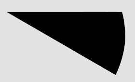
- Add an arc node. Set width and height to 500 and degrees to 30. We want to cut out an arc-shaped slice from our input shape because we can use that to mirror and copy so we can form a kaleidoscope.
- Add an import_svg node. In the file field, press the button and locate your svg file. Make sure the imported shape is centered.
- Add a translate node.
- Connect the output of import_svg1 to the shape port of translate1.
- Add an ungroup node.
-
Connect the output of translate1 to the shape port of ungroup1. This will break up the original shape in different paths. We need a slice from every single path individually or the end result would become just one path in a single color.
- Add a compound node. Change the function to Intersection.
- Connect the output of ungroup1 to the shape1 port of compound1.
- Connect the output of arc1 to the shape2 port of compound1.
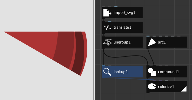
The output of compound1 still looks quite like the arc we started with. Compound operations typically discard all the color information of the original shapes. We have to reset the colors:
- Add a lookup node and inside the field for key, write down fill.
- Connect the output of ungroup1 to the list port of lookup1.
- Add a colorize node.
- Connect the output of compound1 to the shape port of colorize1.
-
Connect the output of lookup1 to the fill port of colorize1. Note that we now have shapes in different colors but that are still within the bounds of our arc.
- Add a group node.
- Connect the output of colorize1 to the shapes port of group1.
- Add a reflect node. Be careful to choose the one that reflects geometry.
-
In reflect1, set the value for angle to 180 degrees. We now have a basic petal that encompasses 60 degrees.

- Add a copy node. Set copies to 6 and rotate to 60 degrees.
- Connect the output of reflect1 to the shape port of copy1.
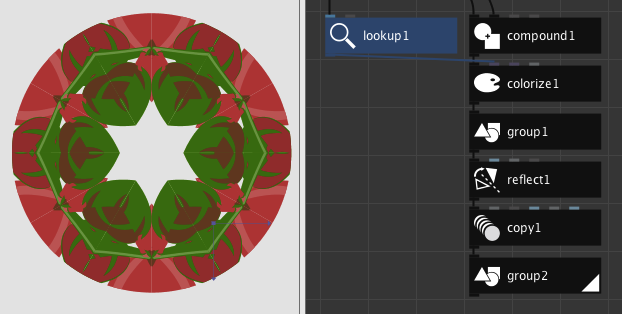
- Add another group node.
- Connect the output of copy1 to the shapes port of group2.
Congratulations, the individual petals now form a full kaleidoscopic pattern! We can take a different slice of our input shape by translating it around:
 To generate this shape, I translated the original shape 111 (x) and 126 (y).
But what if we want a portion of our input form, taken from a different angle? For this we would need to change the start_angle parameter of our arc1 node. However when we try this out, the symmetry starts breaking apart, more specifically at the level of the reflect1 node. We need to counterbalance this by rotating the slice an equal number of degrees but in the opposite direction:
- Between the group1 and reflect1 nodes, add a rotate node.
- Connect the output of group1 to the shape port of rotate1.
- Connect the output of rotate1 to the shape port of reflect1.
- Add a number node and place it somewhere near arc1.
- Connect the output of number1 to the start_angle port of arc1.
- Add a negate node.
- Connect the output of number1 to the value port of negate1.
- Connect the output of negate1 to the angle port of rotate1.
- Rename the number1 node to angle_offset.
If we render our network now, note that there’s now always a smooth transition when we change the value in angle_offset.
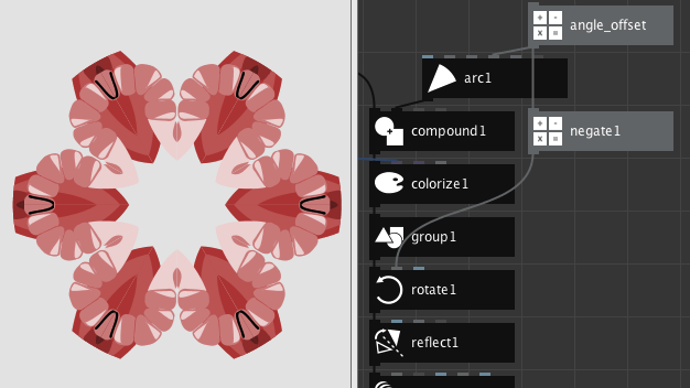 I used an angle_offset of 85 here.
Another thing we’d like to control is the number of petals in our kaleidoscope. Currently it’s fixed to 6 petals. A bit of mathematics can be helpful here:
- Add an integer node and place it near the angle_offset node.
- Rename integer1 to sides. Set its value to 6.
- Connect the output of sides to the copies port of the copy1 node.
- Add a divide node. Set its value1 to 360.
- Connect the output of sides to the value2 port of divide1.
- Connect the output of divide1 to the rotate port of the copy1 node.
At this point we’re already able to control the number of petals but we also have to update the size of our slice accordingly.
- Add a second divide node. Set its value2 to 2.
- Connect the output of divide1 to the value1 port of divide2.
- Connect the output of divide2 to the degrees port of arc1.
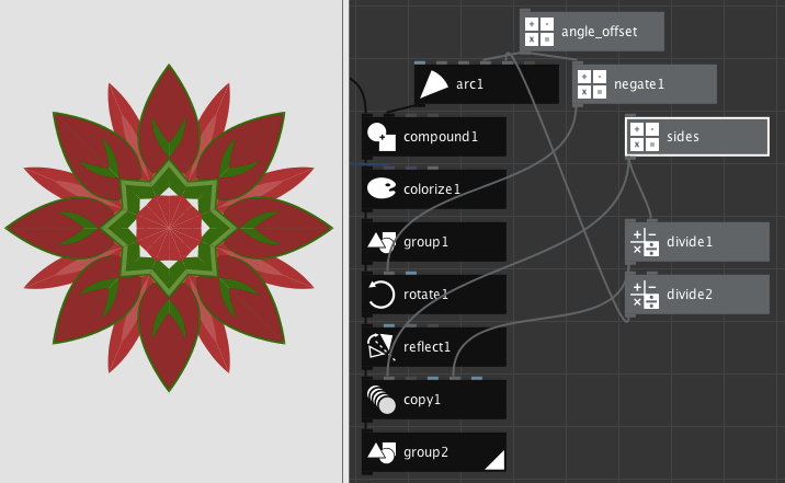 A kaleidoscope with 8 sides.
We would also like to determine the size of our petals by their radius:
- Add a number node.
- Rename number1 to radius. Set the value to 250.
- Add a multiply node. Set its value2 to 2.
- Connect the output of radius to the value1 port of multiply1.
- Connect the output of multiply1 to the width and height ports of arc1.
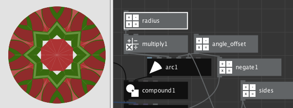 The previous kaleidoscope with a radius of 100.
We now covered all the aspects of the kaleidoscope that we like to control so we can hide the current nodes behind a subnetwork:
- Select all of the nodes excluding your input shape (which if you followed this tutorial is import_svg1).
- Right click on one of the selected nodes and choose Group into Network.
- In the dialog that pops up, enter kaleidoscope.
- Right click on kaleidoscope and choose Edit Children. We want to publish some of the ports to the outer level.
- Go to the angle_offset node and publish the value port. Enter angle as the name.
- Go to the translate1 node and publish the translate port. Enter offset as the name.
- Go to the radius node and publish the value port. Enter radius as the name.
- Go to the sides port and publish the value port. Enter sides as the name.
- Make sure that group2 is still the rendered node of your subnetwork.
- Finally, right click the network view and select Go Up.
That’s it! Your kaleidoscope node is now ready to use. Feel free to play around with the settings and different inputs.
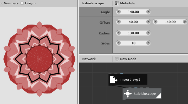 Our final kaleidoscope node!
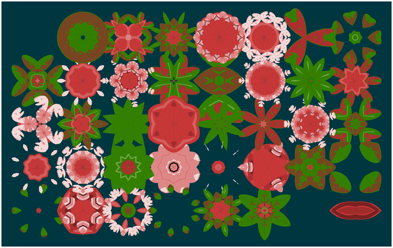
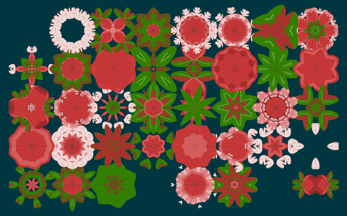 Different variations of the same input shape, laid out on a grid.
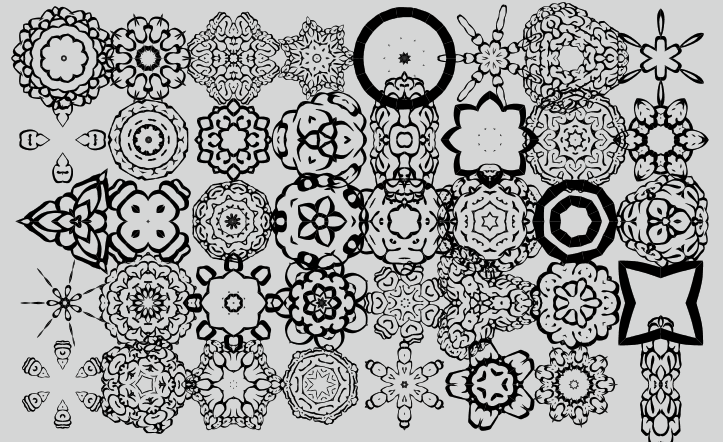 Using a different input source alltogether.