Exploring Nodes
Spirograph Example
Let’s make a drawing based on the Spirograph principle.
In short: we will create a shape and copy it a few times on top of each other with a difference in rotation.
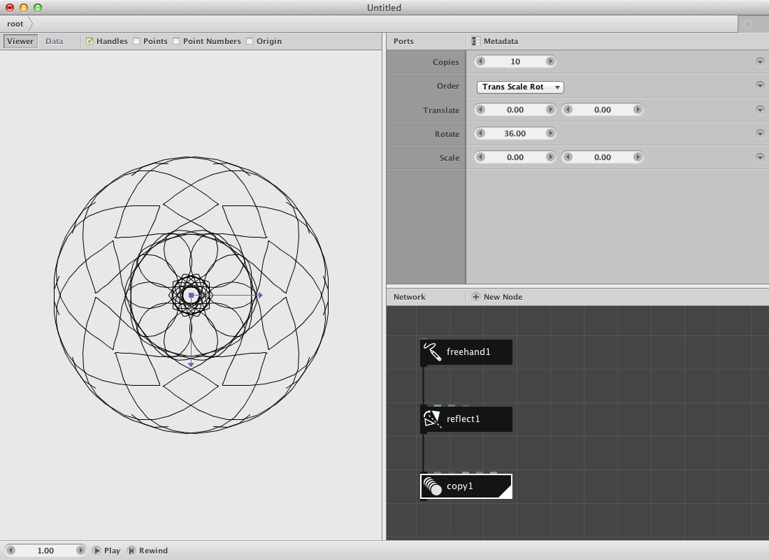
Create a freehand node and draw a small line in order to have a reference for the rest of the procedure. You can draw by clicking and dragging the mouse in the viewer pane.
Create a reflect node node and send the output of freehand1 to it. Watch out: there are two reflect nodes, we need the one with the black icon.
- Change the Angle parameter to 90.00. You should see the change in location of the reflected shape.
- Change the X parameter to 0.0. Dito.
Create a copy node and send the output of reflect1 to it.
- Change the Copies parameter to 10.
- Change the Rotate parameter to 36.0. The calculation of the rotation angle is based on the equation 360.0 / number of copies.
Render copy1 and click once on freehand1. Start drawing something and see the spirograph appear. Not pleased with the result? You can start over and clear the path by pressing the clear button of the path parameter.
Try out:
- Different settings for the parameters in copy1 to create more or less complex spirograph drawings.
- Insert a colorize node node between the freehand1 and reflect1 to experiment with colors.
- Copy the four nodes, make a few variations and group them by sending all of them to a combine node.
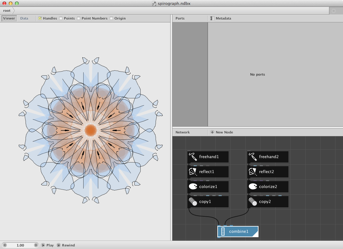
A pattern example.
Creating patterns is fairly easy in NodeBox 3.
Let’s create an example:
Create two polygon nodes.
- Set Radius of both of them to 20.00.
- Set Sides to 5 and 3 to respectively create a pentagon and a triangle.
- Toggle on the Align parameter for both polygons.
The idea is to create a pattern that can be easily changed by using a seed parameter.
Create two wiggle nodes and connect polygon1 to wiggle1 and polygon2 to wiggle2.
- Set Offset to 30 and 30 for the wiggle node handling the pentagon.
- Set Offset to 10 and 10 for the other one.
- Set Seed respectively 0 and 1
We will generate a new shape based on the two shapes by using a binary operation.
Create a compound node and send wiggle1 to shape1 input and wiggle2 to shape2 input.
- Set Function to Difference.
A key node for building networks that create patterns is the align node. It allows you to change the center point of a geometry. The base for these operations on the vertical and horizontal axes is the origin which you can toggle on/off in the viewer pane.
Create one and send compound1 to it.
- Set HAlign to Left.
- Set VAlign to Bottom.
Now create a (black) reflect node to make a reflection of the shape.
- Set Angle to 90
- Turn on the Keep Original option
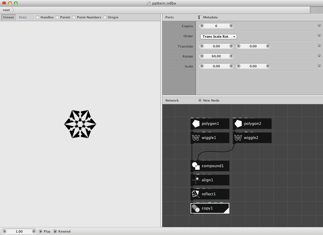
Create a copy node to create a few copies. Connect reflect1 to it.
- Set Copies to 6.
- Set Rotate to 60.00.
The result should look like this:
Add a colorize node to give the shape a color.
Now we will create a grid node to multiply the pattern on a horizontal axis.
- Set Rows to 1.
- Set Columns to 10.
- Set Width to 1000
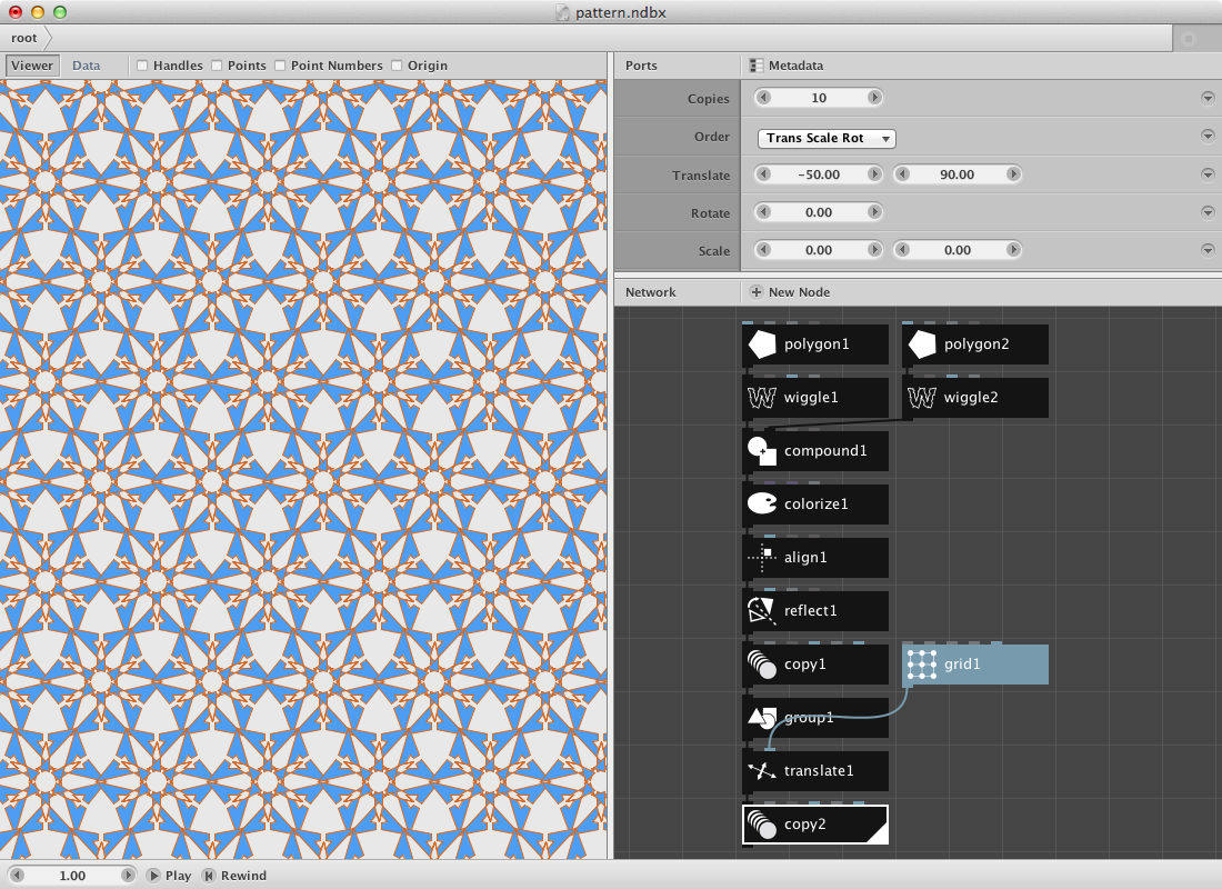
Now add a translate node to the network and send the pattern (copy1) to the shape port and grid1 to the (blue) translate port.
Finally add another copy node and send translate1 to it.
- Set Copies to 10
- Set Translate to -56 and 95
- Scale should remain at 100 and 100
Rendering the copy2 node should return this result:
Try out:
- Change the Seed parameter in one or both of the wiggle nodes to change the pattern:
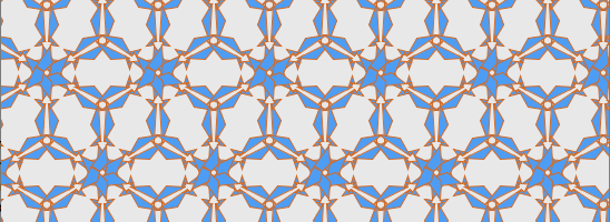
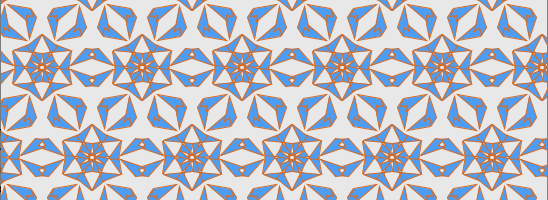
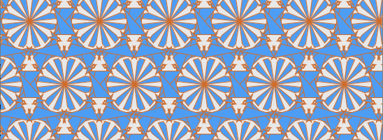
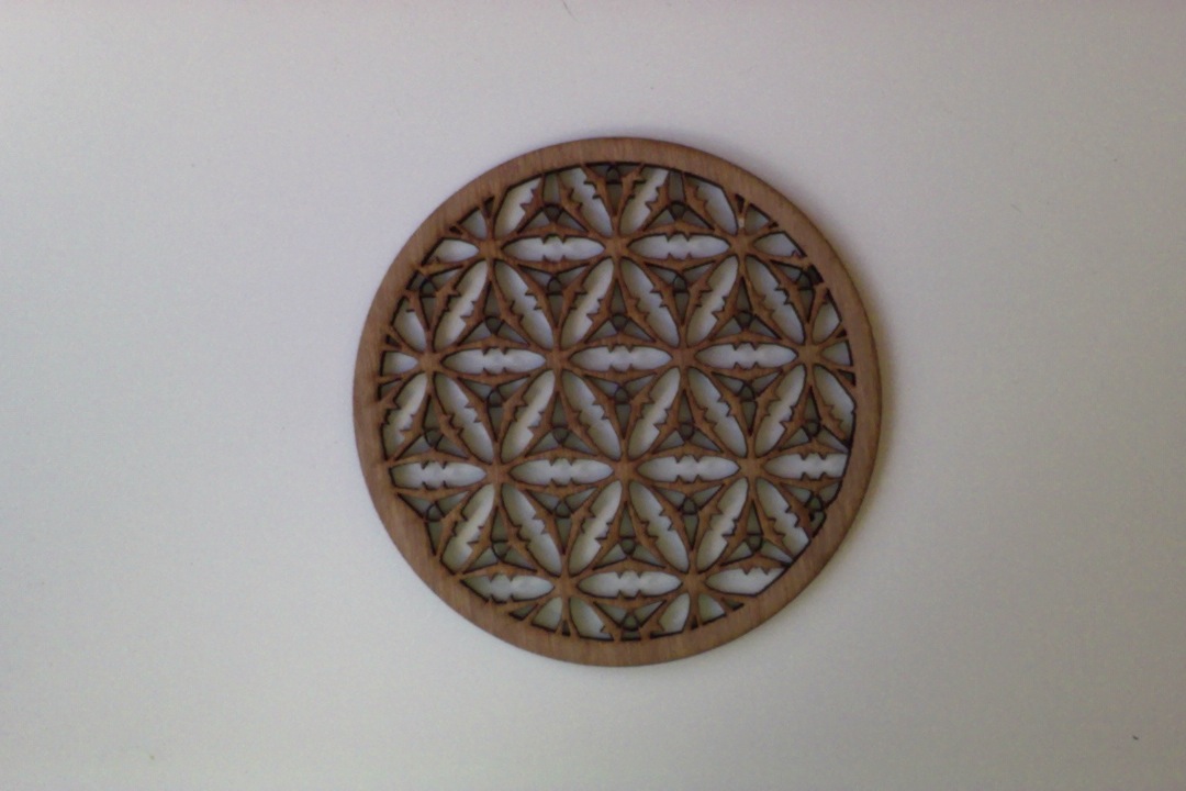
One of the seeds sent to a compound node (together with an ellipse) and cut out by using a CNC-cutter:
A shape example.
Nodebox contains a few nodes that enable users to create a new shape. An interesting one is the coordinates node which can create a point based on an angle and a distance from a point. Let’s see what we can do with it.
Create a sample node and
- Set Amount to 40
- Set End to 360 (since there are 360 degrees in a circle)
Create a coordinates node and send the sample1 node to the angle port. Leave the distance parameter at its default value of 100. You should get a result like this:
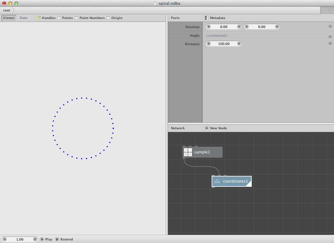
At this moment all points are at an even distance of the orgin point. We will change this by using another sample node. Create one and
- Set Amount to 200
- Set End to 200.0
Send it to the distance port of the coordinates node. The coordinates node returns a list of points, to create an actual path send it to a connect node. Turn the closed parameter off so it does not connect the first point with the last one. This is your result:
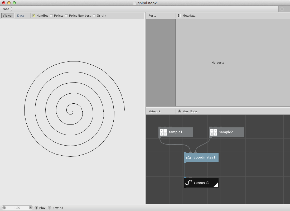
Other shapes can be created by using another set of numbers for the distance and/or angle parameter.
Create a range node and
- Set Start to 50.0
- Set End to 90.0
- Set Step to 10.0
This returns a list of these numbers: 50, 60, 70, 80. Now create a reverse node to reverse the above list. Now send both lists to a combine node resulting in a new list (50, 60, 70, 80, 80, 70, 60, 50). Send the combine node to the distance port of the coordinates node. Render the connect node again and have a look at the result:
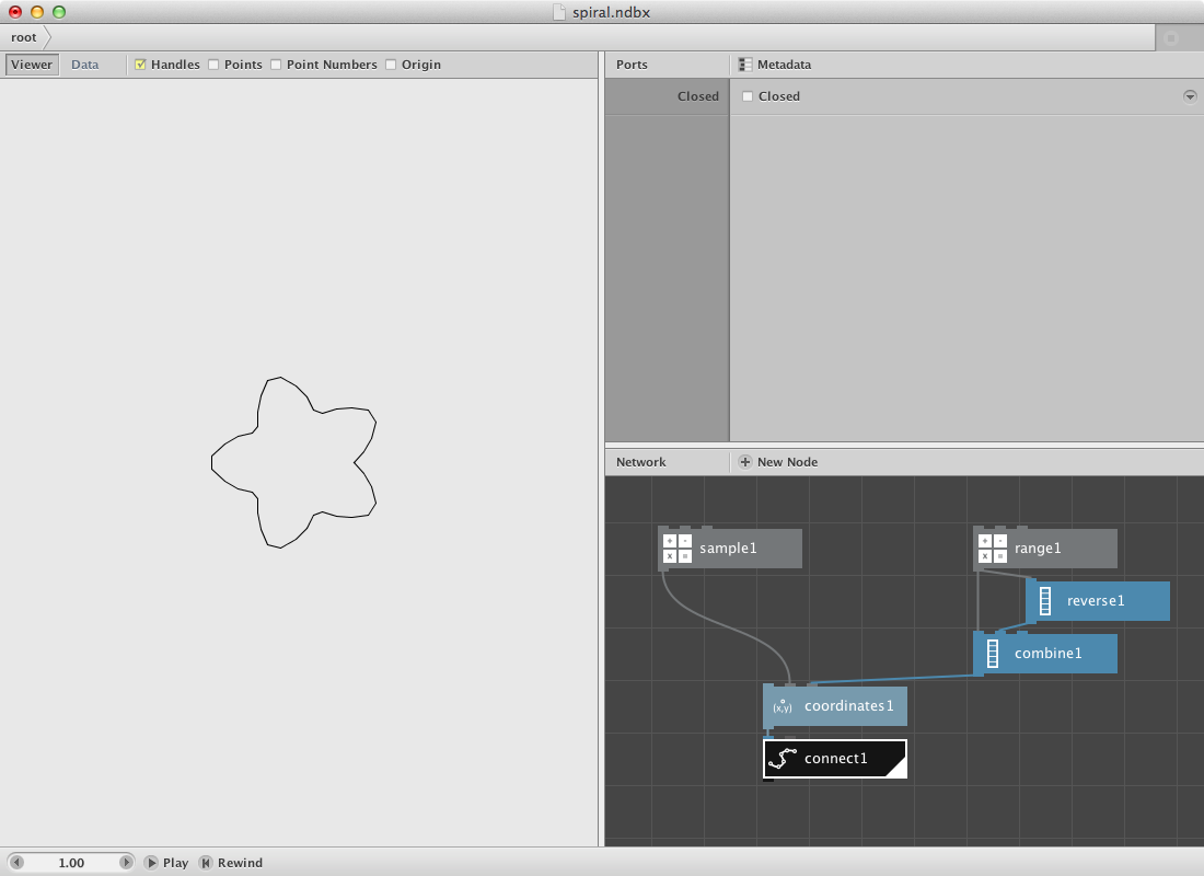
Play around with the parameters of the range and sample nodes. The following shape was created by changing the parameters.
sample node:
- Set Amount to 80.0
range node:
- Set Start to 100.0
- Set End to 150.0
- Set Step to 30.0
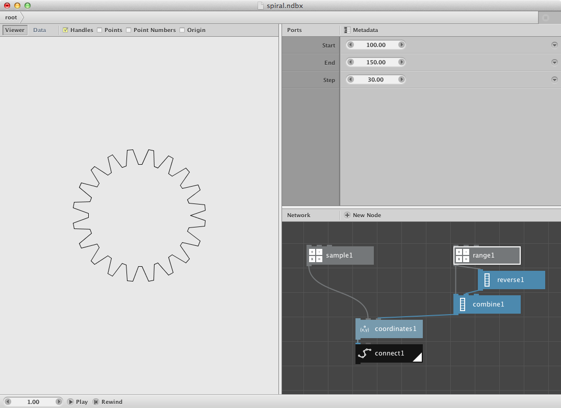
Next Steps
Now that you’ve seen a few examples, you can:
- Animate: See the basics of animation.
- Learn the GUI: Discover all functionality of the NodeBox GUI.